The CAMAG TLC Scanner 4 is the most advanced workstation for densitometric evaluation of TLC/HPTLC chromatograms and other planar objects.
Key features
• Measurement of reflection, either in absorbance or fluorescence mode
• Object formats up to 20 x 20 cm
• Spectral range from 190 to 900 nm
• Automatic start of all lamps: deuterium, halogen-tungsten, and high pressure mercury lamp
• Data step resolution 25–200 μm
• Scanning speed 1–100 mm/s
• Spectrum recording up to 100 nm/s
• Automatic selection of electronic amplification
• Rapid data transfer
• Meets all requirements to be used in a cGMP/cGLP environment
• IQ/OQ qualification and 21 CFR Part 11 ready
Evaluation with visionCATS
visionCATS controls the CAMAG TLC Scanner 4 and enables quantitative evaluation of the generated densitometric data. To determine the substance concentration in a sample, five different quantification functions (e.g. linear and polynomial) are available. Several scanning steps (e.g. scanning the plate after development and scanning the same plate after derivatization) and up to five different evaluations can be performed (with data obtained from single wavelength, multiple wavelengths or a combination of measurements in absorption and fluorescence detection mode).
The Scanner Ultimate Package
• Multi Wavelength: this feature offers the possibility to perform a multi-wavelength scan with up to 31 selected wavelengths or a combination of measurements in absorption and fluorescence detection mode.
• Scanner Quantification: this feature allows to quantify each individual substance on the plate. Five different quantification functions are available for evaluation to determine the concentration of the substance in a sample. In one analysis file up to five evaluation steps can be performed in multiple plate states (e.g. plate after development and same plate after derivatization).
• Spectrum Scanning: this feature includes the measurement of the spectrum of each individual substance on the plate including the evaluation of the substance purity by comparison with reference standard.
Examples with visionCATS
Peak Assignment
The separated compounds are assigned. For quantification, data from the multi-wavelength scan at the optimum wavelength for each compound is used. 
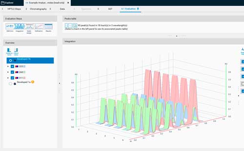
Densitograms are displayed in 3D, top or front view. Several peak integration and baseline correction settings can be selected.
Calibration CurveFor evaluation the best fitting calibration model is used. Quantitation can be done via peak height or area.
The Optical System•
Any of the three light sources, high pressure mercury lamp, deuterium lamp, or halogen-tungsten lamp can be positioned in the light path by a motor drive. (1)
•
The signal of the measuring photomultiplier is continuously offset against the signal of the reference photomultiplier. (4 and 5) This compensates for lamp aging and short-time fluctuations. It also reduces the warm-up time required to reach lamp stabilization.
•
All components of the optical system, lamps, monochromator, scanning stage, and photomultiplier are mounted on one sturdy metal support. This ensures high precision of the detector signal.
•
For scanning at wavelengths below 200 nm it is advisable to flush the monochromator with nitrogen. The scanner is equipped to do this.
•
A monochromator bandwidth of 5 nm or 20 nm can be selected. 5 nm bandwidth is used for spectra recording, multi-wavelength scanning, and when spectral selectivity is required. (2) 20 nm bandwidth offers higher light intensity (improves the signal to noise ratio and thus the reproducibility of the measurement) and enables measurement of several fractions with slightly different absorption maxima in one scan.
•
The lens system with 190 – 900 nm transmission range features automatic positioning for micro and macro slit sizes. This ensures that the light energy available with small slits in the micro position is almost the same as that for the corresponding slit in the macro position, which is four times larger. (3)
•
The light beam strikes the object at right angle. The photomultiplier is aligned at an angle of 30°. (5)